M3S: Calibration
In Part 7 – DSP we used a miniDSP to tune our subwoofers specifically for the Model 3. In that post I mentioned a mysterious
As I mentioned in the intro, I really want these posts to offer new information instead of simply recreating the wheel. Since other people have already covered the Model 3 power system and how it’s different from ICE cars, I don’t want to go deep into that here. If that information is new to you, though, I highly recommend reading Travis Llado’s Part 9.
One part of Travis’ guide that I struggled to completely wrap my head around was this wiring diagram:
While the diagram clearly showed me which components connected to which, I was having trouble envisioning which wires connected where. Travis posted another diagram that I found very helpful in this regard though, the one for his trickle charging circuit:
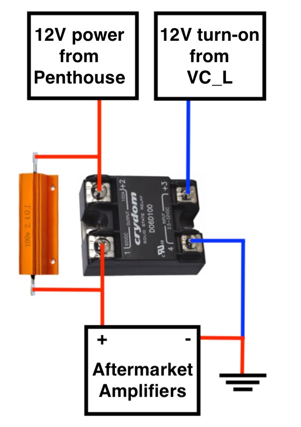
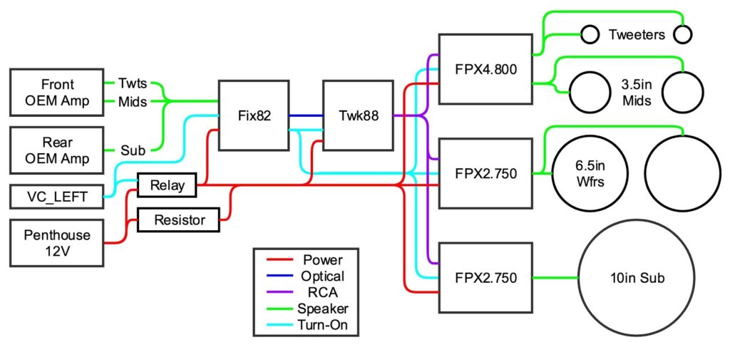
When I started my project, I kept wishing I had something like that for the entire power system. So, for you dear reader, I’ve created exactly that.
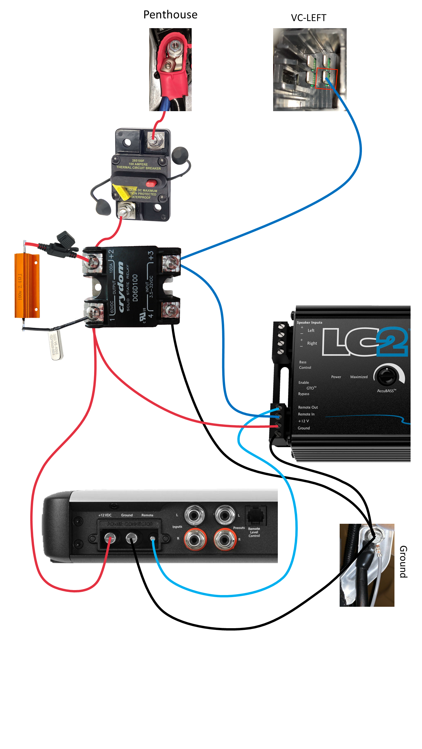
This diagram shows where every power wire connects including where it connects to the vehicle. You can click the image above to view a larger version, and if you click the ‘Expand’ button in the popup lightbox you can see the full diagram at its native resolution.
To simplify things I did leave out the fused distribution block, but I hope it goes without saying that every piece of equipment should be fused accordingly. In Part 4 – Tap and Layout we’ll see the final install, which includes these components.
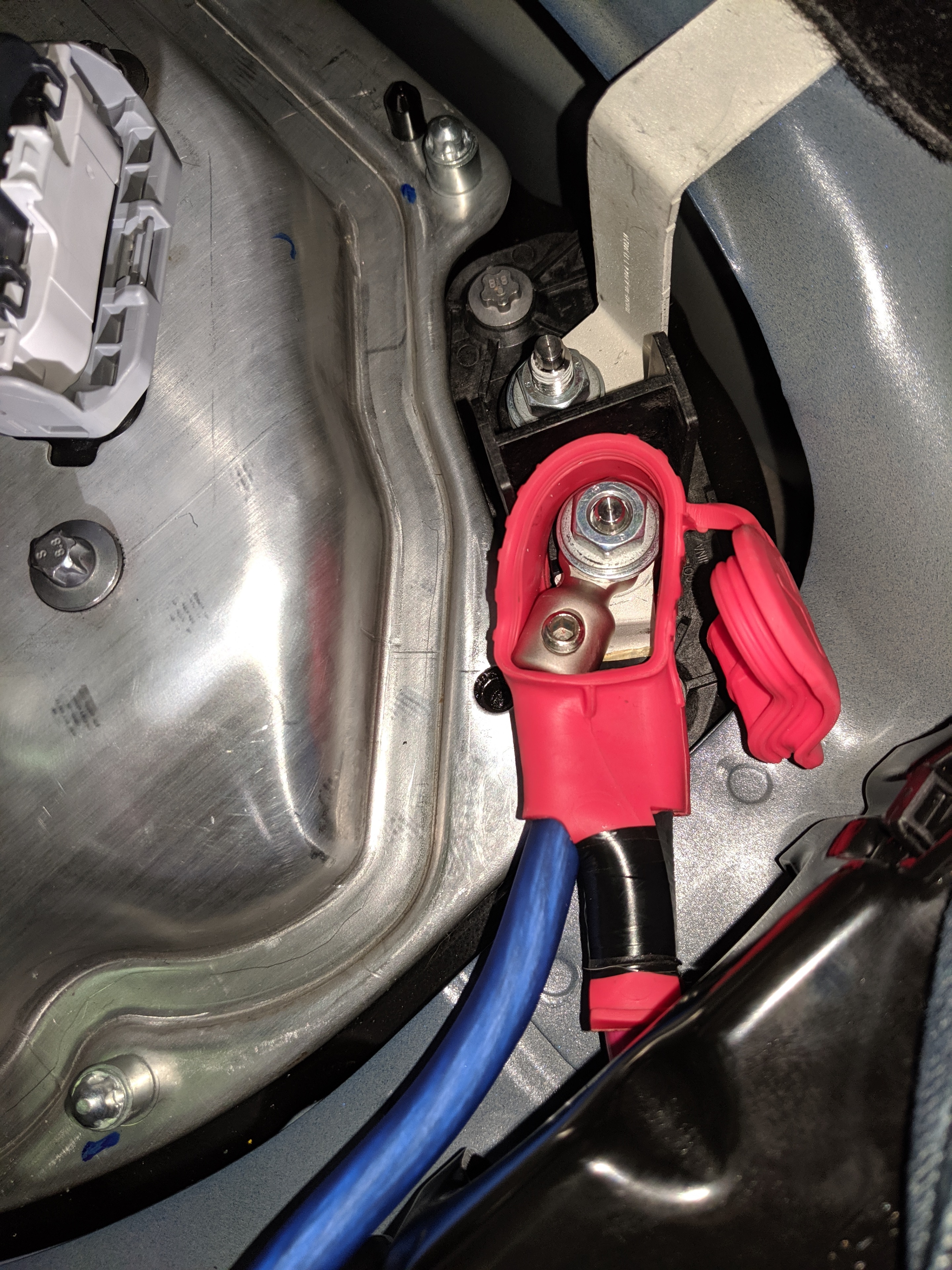
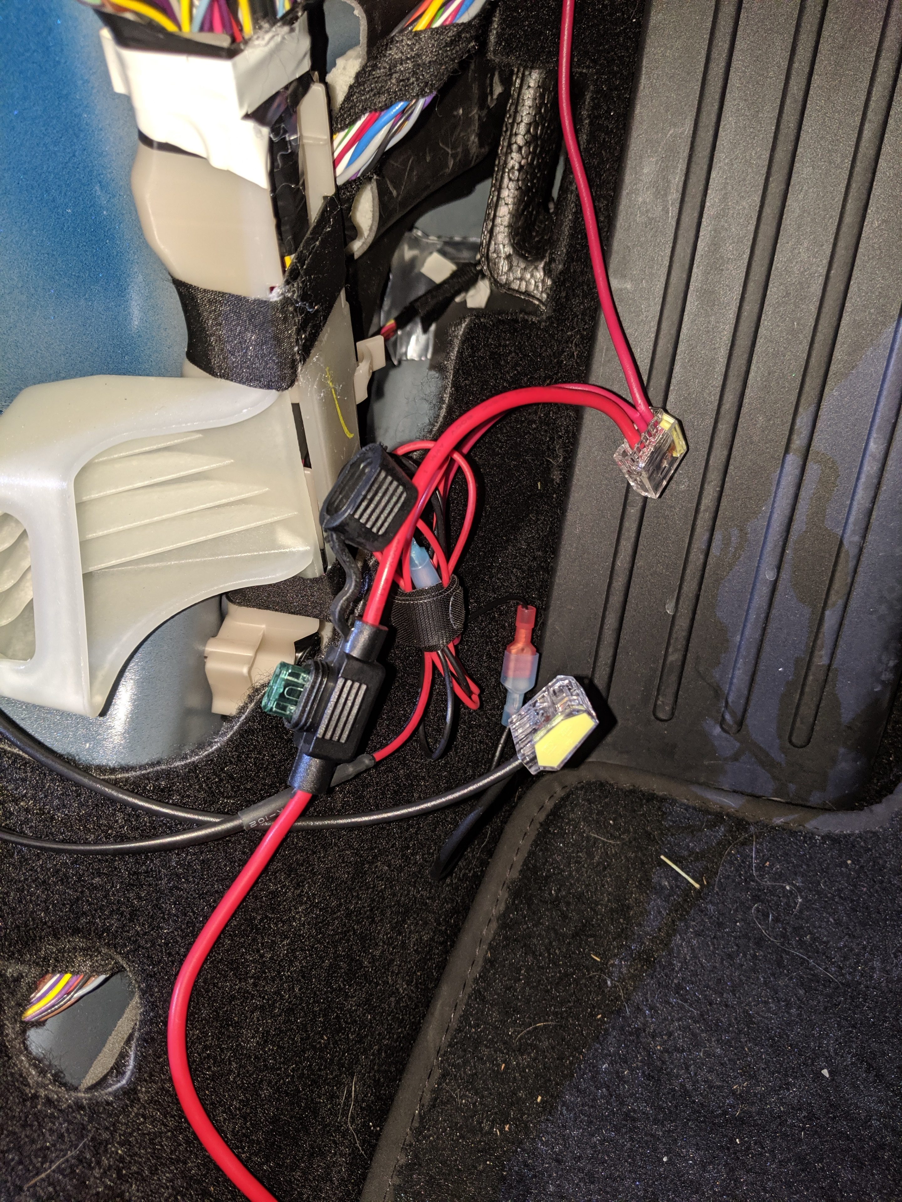
I also wanted to share a little more detail than what others have posted so far on tapping and routing power. Here’s a close-up of how I tapped the Penthouse.
As with any car audio project, it’s important to install a fuse or circuit breaker as close to the power source as possible. I installed a 100 A breaker underneath the passenger seat very close to the tap.

The only thing I was slightly concerned about here was that I still had an exposed and unprotected terminal.
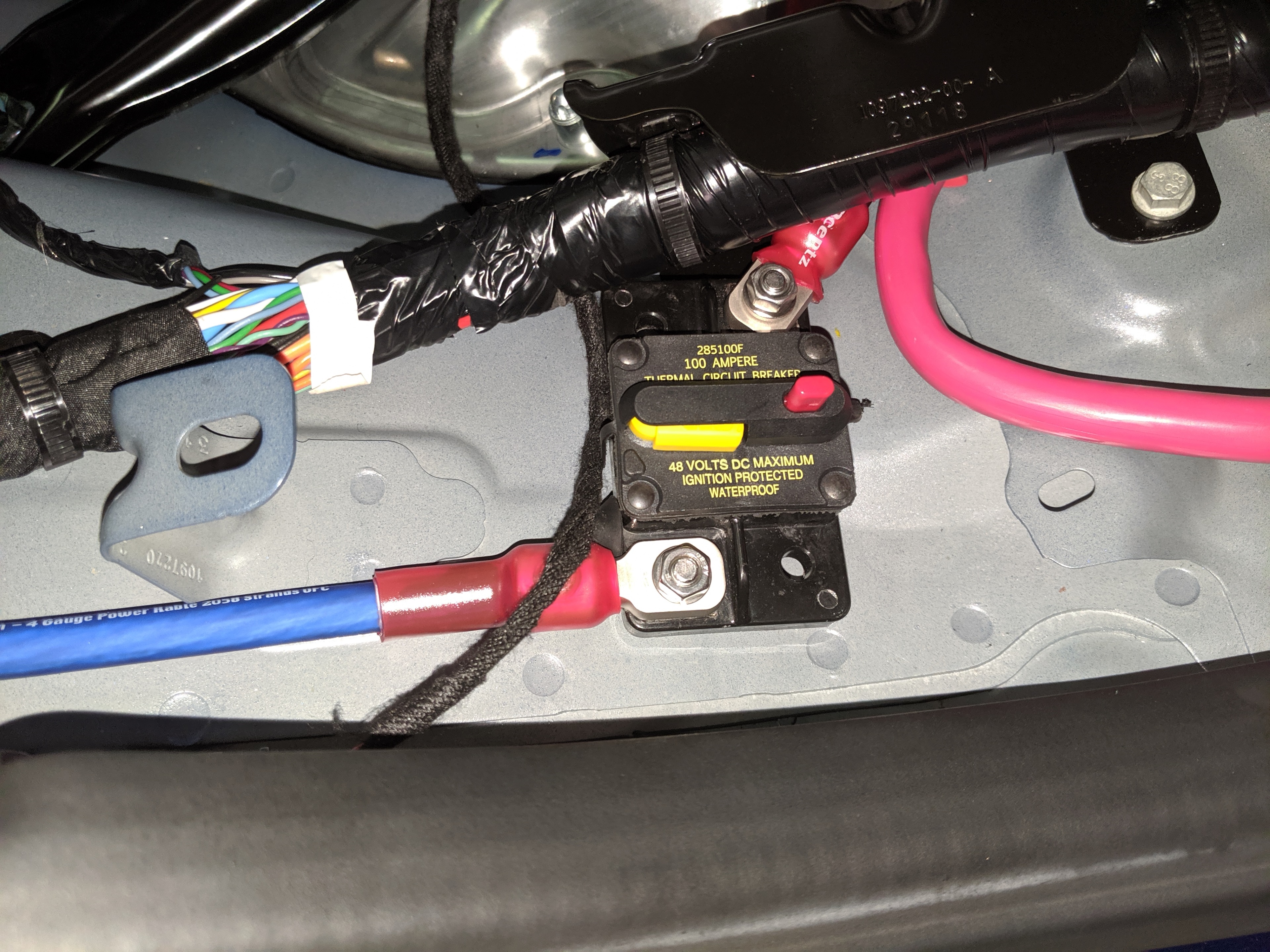
Since it’s under the seat I wasn’t really worried about something dropping onto it, but I was concerned about hitting a bump and that terminal somehow coming into contact with something above it.
I ended up painting over both terminals with several coats of green liquid electrical tape. I also added a strip of gorilla tape over the source terminal, for added safety and to keep the breaker from sliding around.
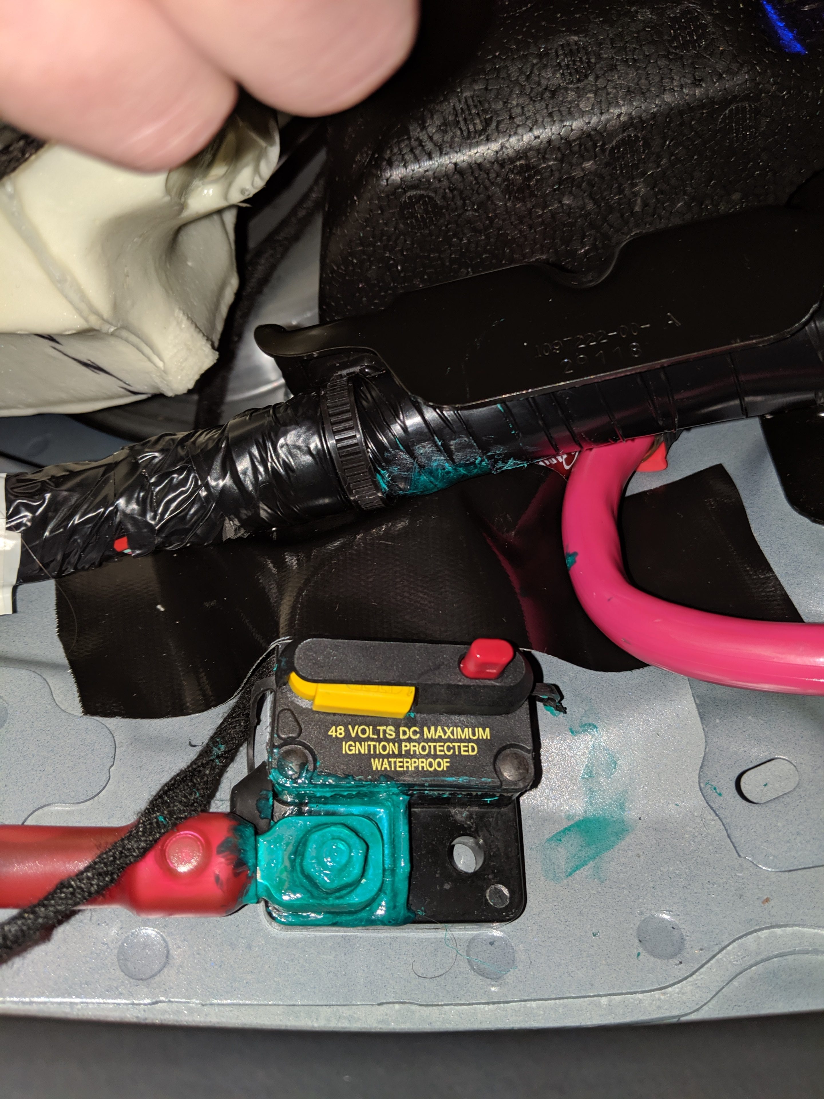
Admittedly my paint job wasn’t that great. It’s not pretty, but it is hidden under the seat so I’m not overly concerned about aesthetics.
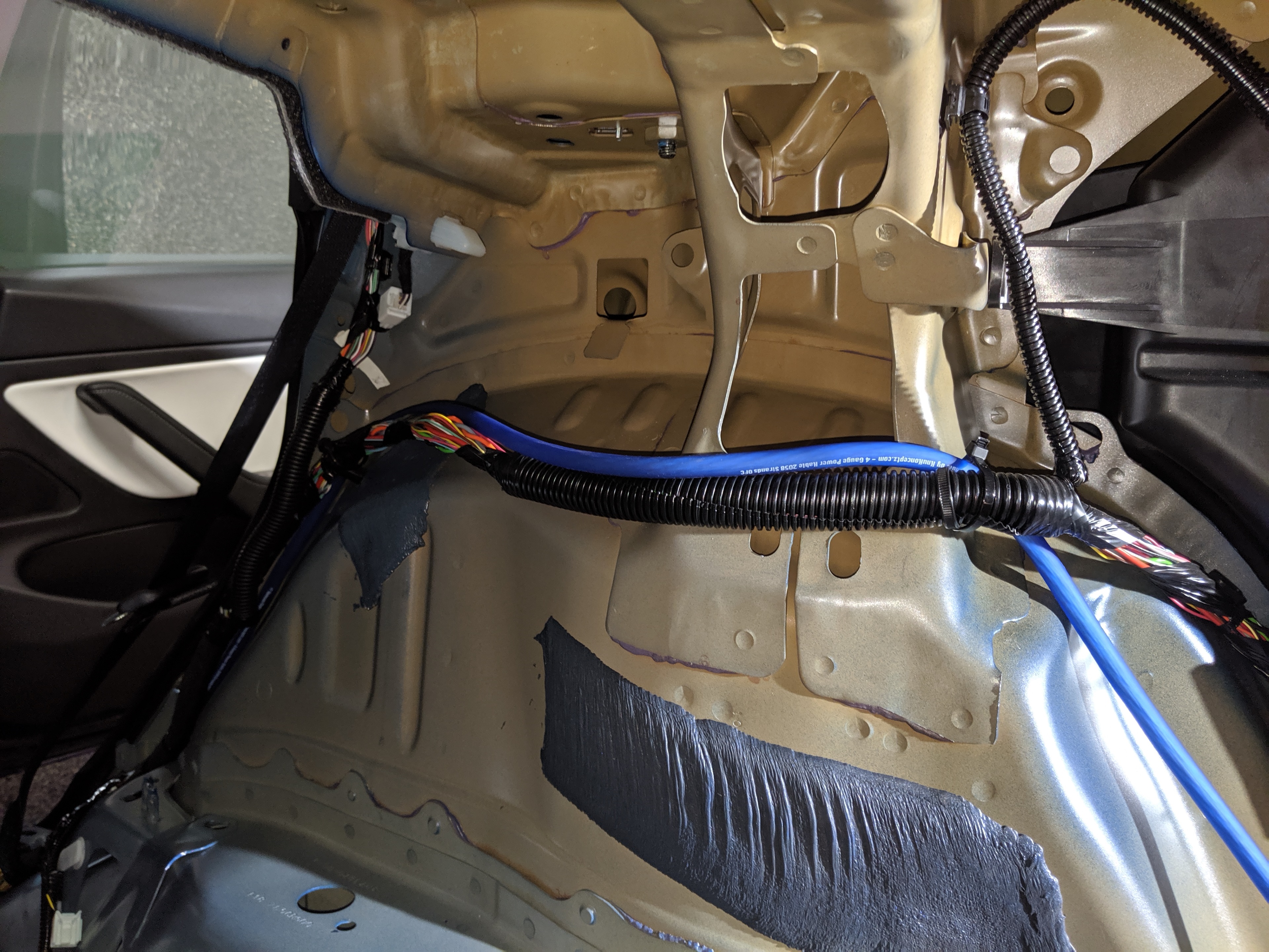
From there I ran the power wire up and over wheel well, following the same path as the bundle of wires that was already there.
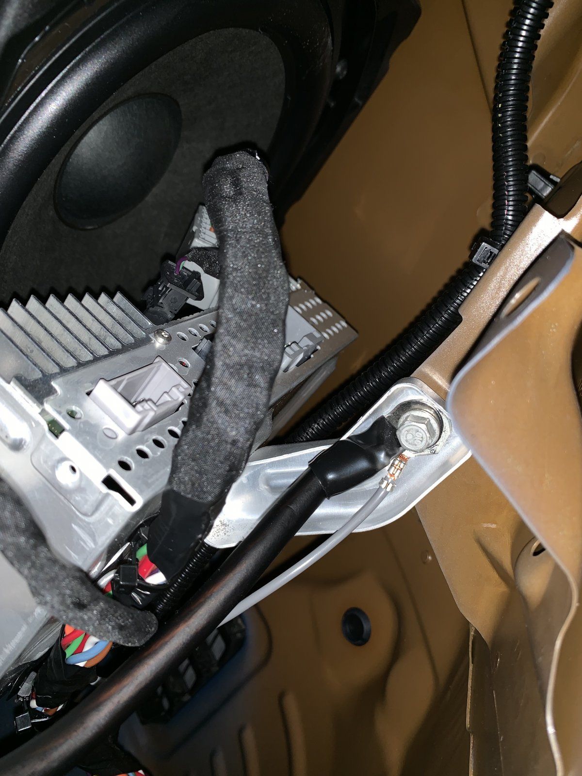
After power comes ground, and for this I went the same route many others have before me: I just used the same bolt that the stock amplifier uses. I forgot to get a photo of it so I’m going to borrow one from Cookiebob.
After ground it’s time to run the remote wire from VC_LEFT to the trunk. This part was fairly easy for me because I’d previously tapped VC_LEFT for my radar detector. Luckily, I had the foresight at the time to use push connectors and leave them tucked away behind the kick panel. This made it really easy to add the remote wire (as well as any other accessories I’d like to add in the future).
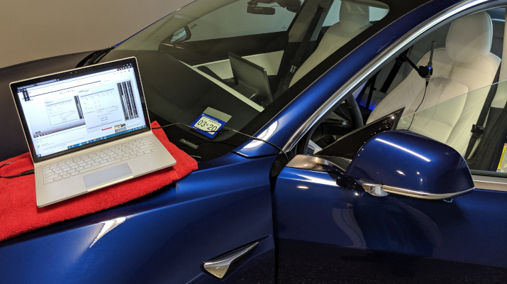
With the electrical components done, it was time to set up the trickle charging circuit and try things out for the very first time! (Don’t worry, I’ll cover tapping the audio system in Part 4).
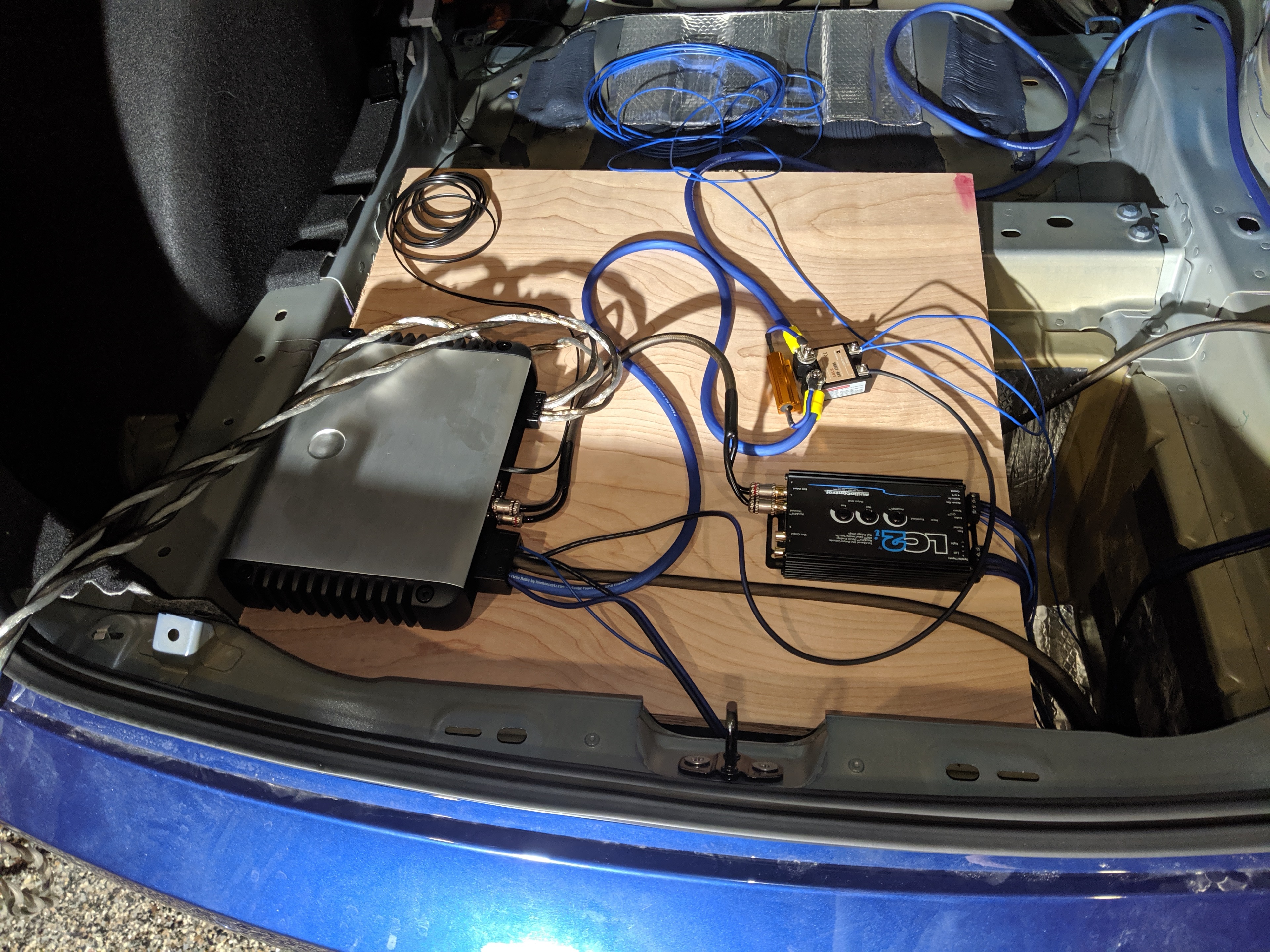
I was really excited when equipment lights came on and big booming bass came out! But something wasn’t right. The bass was cutting in and out every half second. And when I looked at the LC2i, I could see the power light dimming and coming back on every time the sound cut out. My heart sank. I thought my LC2i was faulty. And since I’d ordered it from Amazon, I knew it was going to be at least 2 days before I could get a replacement. But then, by chance, I put my hand on the resistor and yanked it away in pain. The resistor was hot hot HOT!
Clearly there was a problem, but what? I had already double-checked every connection before powering it all on. I’d even tested the relay to make sure it was working. But if the relay was truly working, power shouldn’t be going through the resistor and it certainly shouldn’t be getting that hot.
At the time I figured the relay must be faulty, since it seemed to work fine when the amplifier was disconnected but it stopped working when the amp was attached and the relay under load. And this relay may have in fact been faulty, but I also realized later that I bought an AC switching relay and not a DC switching one. I had no idea that solid state relays didn’t work entirely like their mechanical counterparts. Again, following what Travis did, I returned my cheaper SSR and bought the (much) more expensive Crydom one.
It took a few days for the Crydom to arrive, but once it was in place everything worked like a charm. Still… I couldn’t stop thinking about how hot that resistor got and it made me worry about what might happen in the future if the Crydom ever went out. I brought this up in the forums and the general consensus was to add a 5A fuse before the resistor. But that still didn’t put me completely at ease because 5A @ 13.5V would still allow 67.5 watts of power to flow through the resistor. Enough, I believe, to still get quite hot.
I did finally come up with a solution I’m happy with, and I want to share the plans for that solution now.
11/23/2009 – Thermal Update 1 – On October 28 2019, Jamie Sibley reported that his own charging circuit malfunctioned and caused a small fire. Jamie said that his relay wasn’t working, and he believes that enough current passed through the resistor to make it red hot and catch nearby wires on fire. Though Jamie never shared any photos of the incident, I decided to update my design to include a thermal relay as a precaution. The parts list below, as well as images and instructions, have been updated to incorporate this change.
01/29/2020 – Thermal Update 2 – Over the holiday I continued monitoring the temperature of the Solid State Relay (SSR). I also took some video with a FLIR camera, which you can view below. Looks like the SSR can get quite hot under load. It reached 135 F in about 7 minutes of heavy bass when not mounted to a heat sink. I don’t know what the peak is when mounted to a heat sink and loaded over time. At first I thought it was maybe the resistor, but clearly it’s the SSR. I’m not currently happy with this solution and I’m actively looking for alternatives.
| Crydom D06D100 Solid State Relay |
| 12.5mm x 7mm x 5mm Aluminium Heat Sink |
| 100W 2.4 Ohm Aluminum Case Resistor (Preferred) |
| 100W 2.0 Ohm Aluminum Case Resistor (If above is out of stock) |
| Thermal Relay Assortment Kit |
| Mini Blade Fuse Holder |
| 5A Mini Blade Fuse (Here’s a good assortment) |
| M4 Screws (Here’s a good assortment) |
| Thermal Paste |
| Bondic “UV Welder” or similar |
| Small Gauge Fork and Female Spade Connectors (good assortment) |
| Large Gauge Fork Connectors (whatever gauge for main power) |
| Heat Shrink Tubing (good assortment) – Optional but recommended |
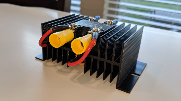
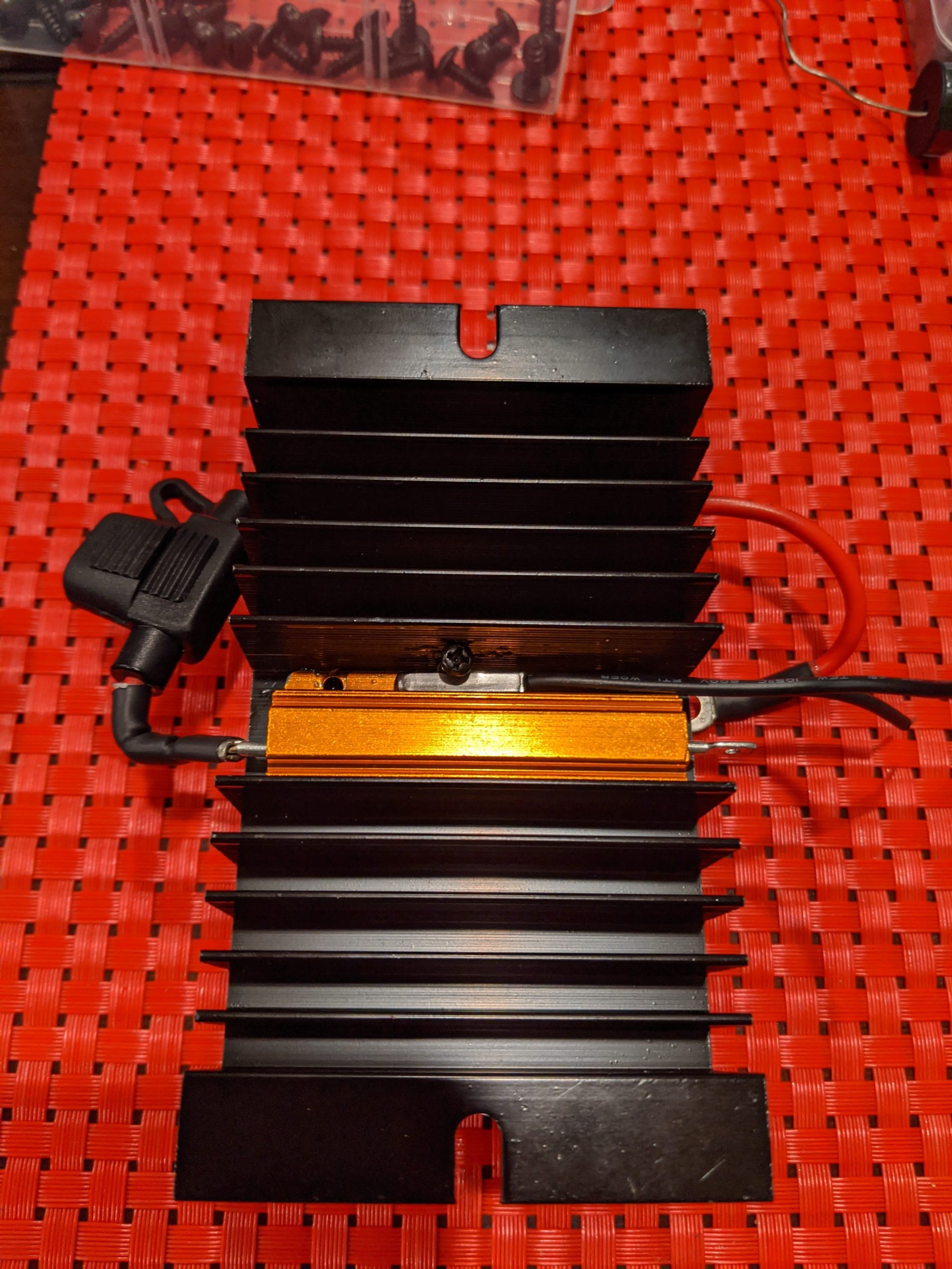
Here’s a photo of the (mostly) finished part:
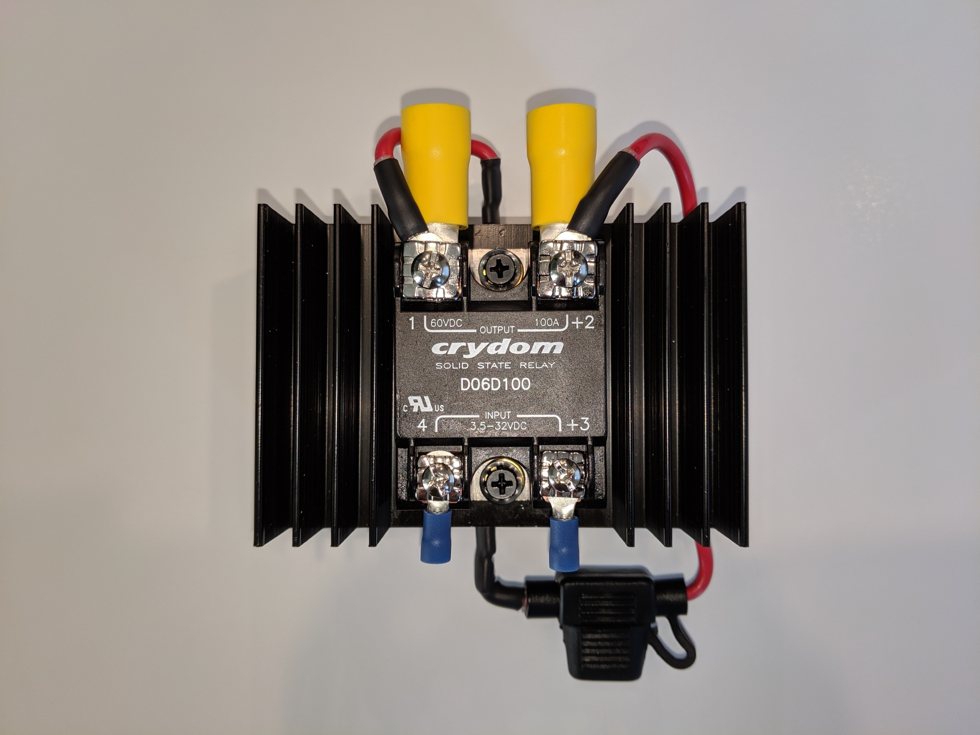
It’s optional, but I used small female spade connectors like these:
To securely “grip” the connectors on either end of the resistor. I did this so if anything ever goes wrong with the resistor I can replace it without having to cut and re-solder wires. You can see these connectors in use at the top and bottom of this photo:
This photo also shows that the resistor is mounted into the channel underneath the relay. This is tricky because the resistor is just a tiny bit too big to fit. You’ll end up having to grind about 1/16th of an inch off either side of the resistor. I recommend the side with the mounting holes. I used a Dremel with a grinding bit for this but heavy grit sandpaper would work too. Once the resistor fits into the channel it needs to be secured so that it won’t fall when you go over a bump. That’s what the Bondic is for, but before you use the Bondic don’t forget to apply some Thermal Paste between the resistor and the heat sink. While you’re at it, apply some thermal paste between the relay and the heat sink, too.
Now, as I mentioned above, I decided to add a thermal relay to this circuit as well. I recommend using both the thermal relay and the fuse, but you can probably get by with just the thermal relay. The reason the thermal relay was added is because the resistor can get very hot without without actually blowing the fuse. This is the main reason while the whole circuit is mounted to a heat sink, but the thermal relay adds an extra layer of protection. The thermal relay lets you select a temperature above which the circuit won’t operate. If the primary relay ever fails, and if the resistor ever gets hot, the thermal relay will cut power to the circuit until the temperature falls back below this threshold.
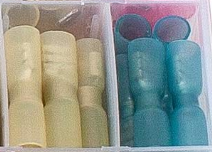
If you buy the same thermal resistor package, the contents of the package look like this:
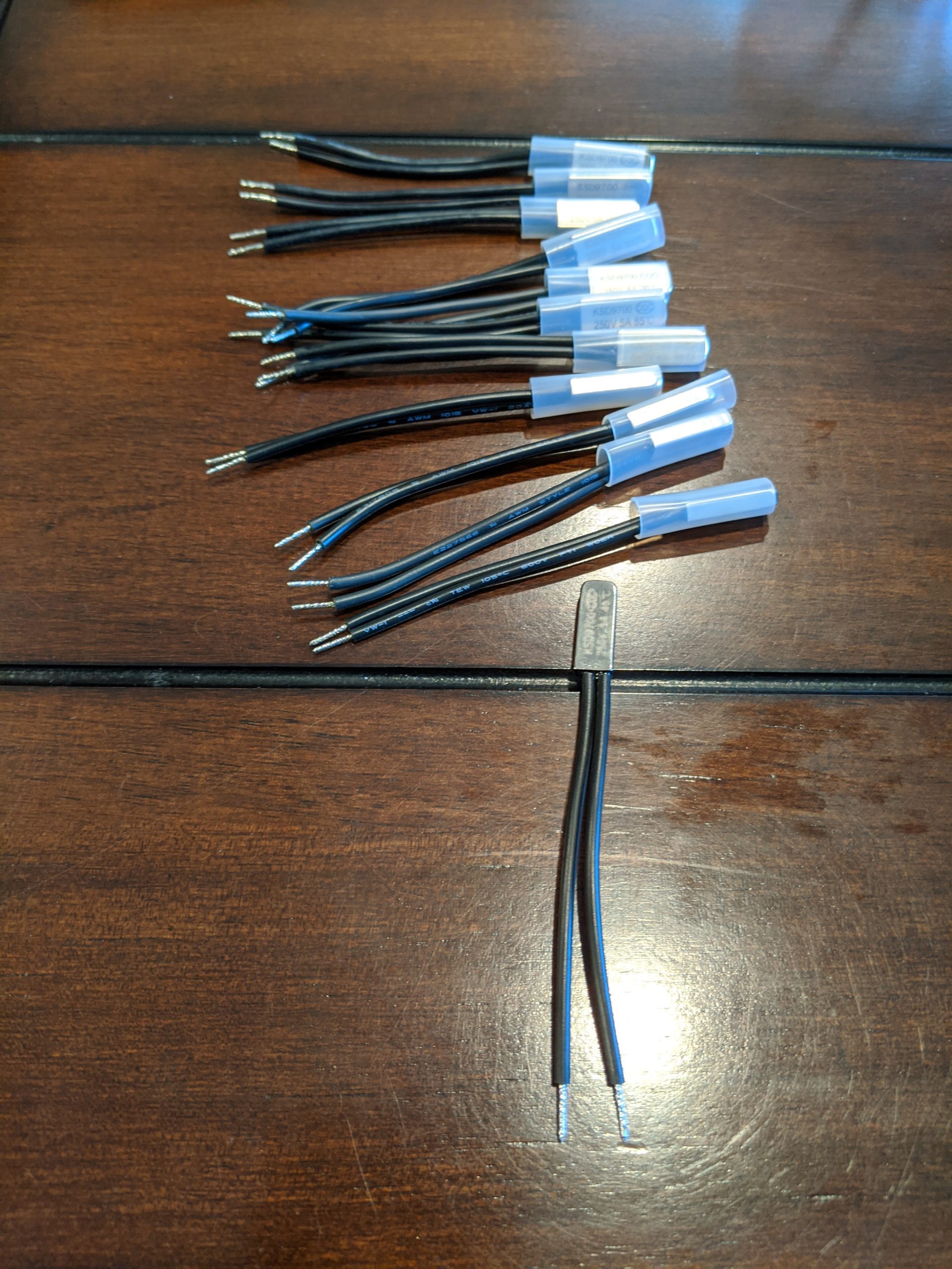
Each individual relay has a temperature printed on the side. This temperature is supposed to be the temperature at which the relay will cut out, plus or minus 5 degrees Celsius. But I tested several of these relays and the cutout point wasn’t what I expected.
I started by plugging each relay into a multi-meter that plays a beep as long as the relay is “on”.
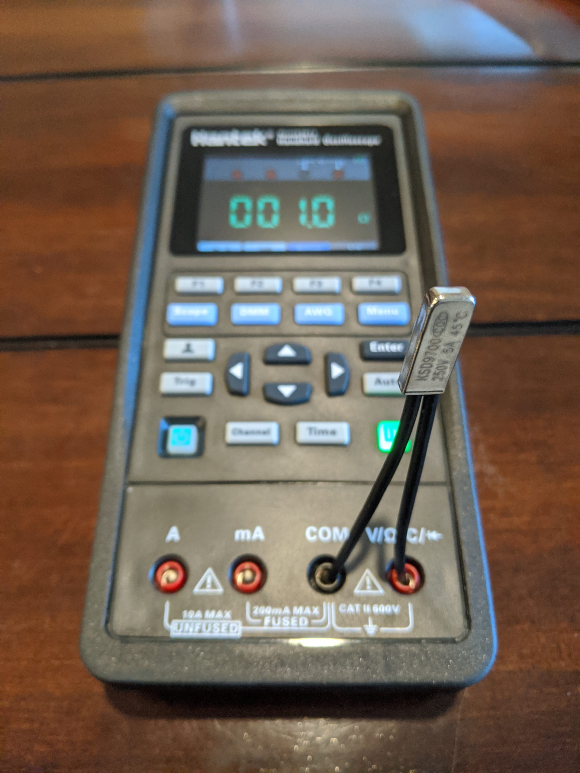
Then I held a temperature probe to the side of the relay and started heating the relay with a lighter.

The moment beeping stopped, I took a note of the temperature.
The relay marked 80C cut out around 140F (80C = 176F)
The relay marked 85C cut out around 150F (85C = 185F)
The relay marked 90C cut out around 170F (90C = 194F)
Moral of the story: be sure to test the relay and not depend on what’s marked on the side.
But what temperature thermal relay should you choose? I recommend using Car Temperature Calculator and plugging in the values for your area. In Houston it’s possible for interior temperatures to reach over 140 F. And here’s a video of a car in Arizona hitting 192 F. Basically, pick a relay that’s just above the max temperature for your area.
With the thermal relay selected, place it in the same groove as the resistor and secure it in place. I used a small screw to ensure the thermal relay is pressed up tight against the resistor.
Don’t use too large a screw here or you risk damaging the relay housing. Damage to the housing could prevent the internal mechanism from doing its job, which defeats the whole purpose. You might wonder why I didn’t just use Bondic here? I didn’t want to depend on the Bondic not breaking down if temperatures started to climb.
After the thermal relay is secured, connect one end of the thermal relay to the resistor and the other end to the Crydom. Refer to the Power Diagram at the top of this page if you have questions on connections.
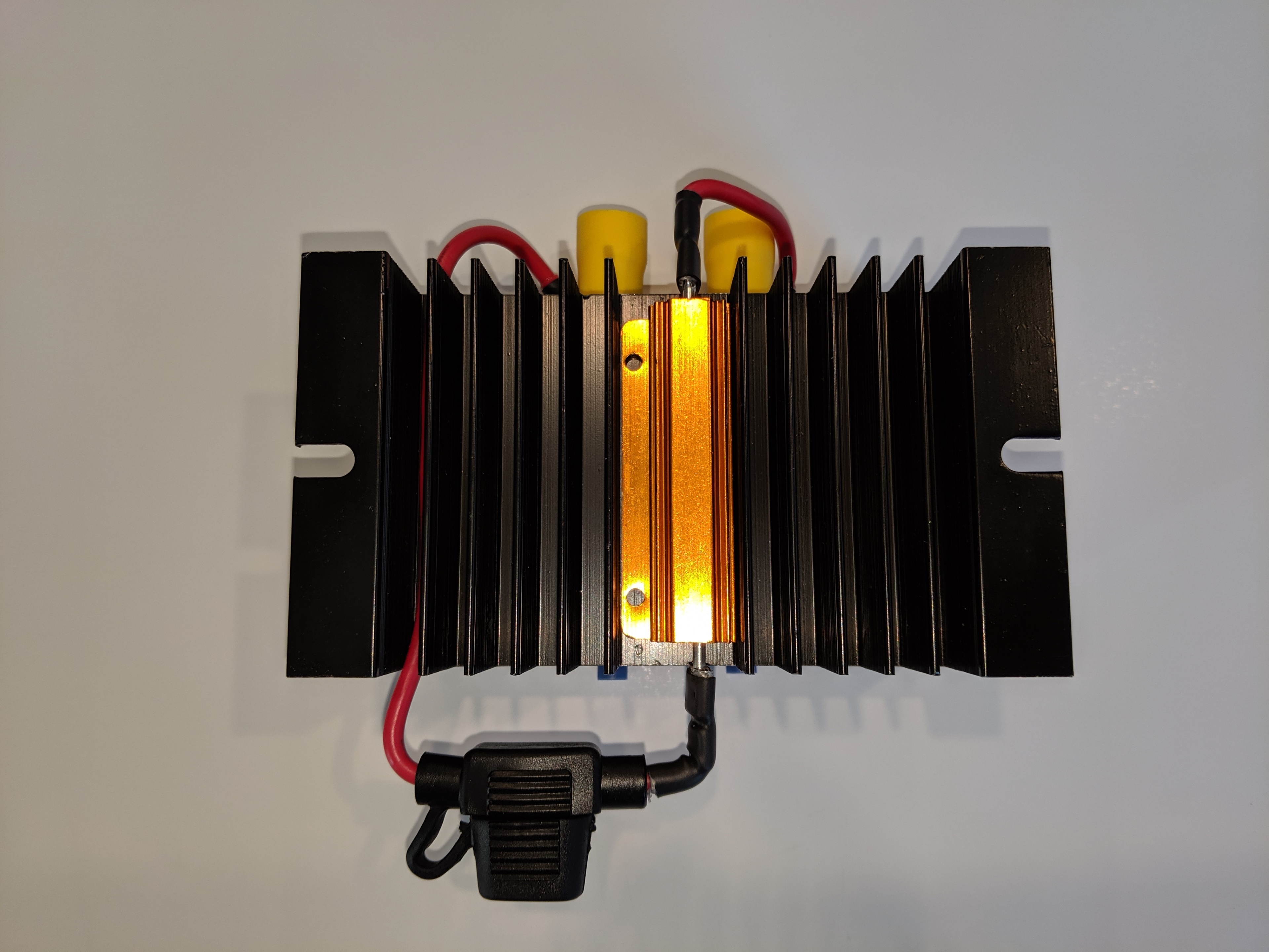
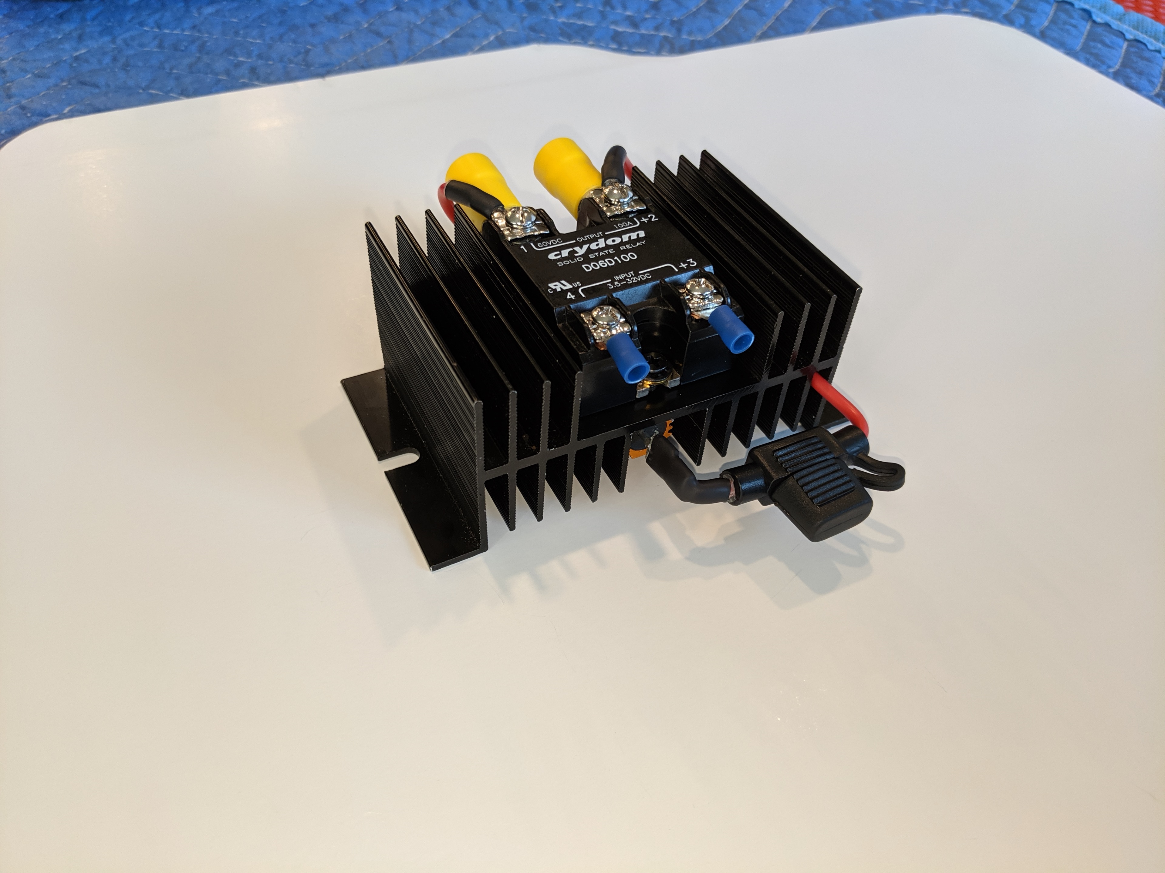
Below are two more photos that show how it all comes together, but please note that these pictures do not include the thermal relay. You would see the relay connected between the resistor and Output Pin 1 on the Crydom.

Well that’s it for Power!
In Part 4 – Tap and Layout we’ll connect to the Model 3 stock system and finally see all the parts come together on the equipment board.
In Part 7 – DSP we used a miniDSP to tune our subwoofers specifically for the Model 3. In that post I mentioned a mysterious
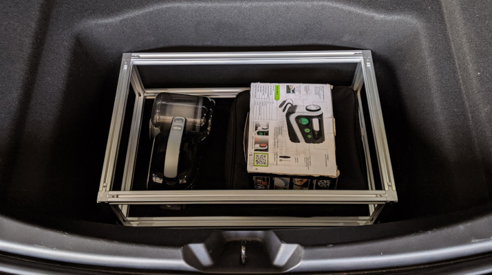
Though I was willing to give up nearly 50% of my trunk, I really didn’t want to give up on storage space entirely. I still