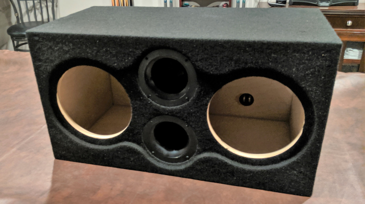
M3S: Enclosure
I can hear you now: “Really? The entire first post in this series is dedicated to an enclosure?” But hear me out. I learned quite
As tremendously valuable as the aftermarket sound system thread has been, there’s one critical piece of information that no one seems to agree on: How to tap the stock subwoofer.
Problem is, if you’re not paying really close attention it’s easy to think everyone’s in agreement. But let’s take a look at some of the discrepancies.
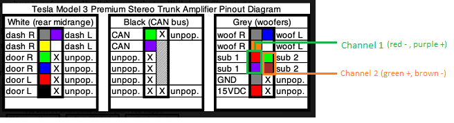
First, this post from R1Fast shows the following pinouts for the stock amplifier:
Then there are these pinouts from Travis’ blog part 9:
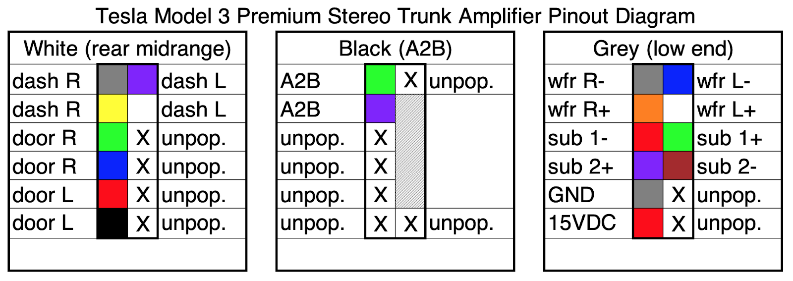
Those pinouts look similar, but they’re not the same. R1Fast shows voice coil 1 to be Red and Purple, while Travis shows voice coil 1 to be Red and Green. Even though they don’t agree which coil is where, they at least both agree which pins are minus (-) and which are plus (+).
Then there’s this post from Cookiebob showing how he tapped the sub:
In that photo Cookiebob appears to tap Red as plus (+) and Green as minus (-), which is opposite what R1Fast and Travis both documented. Interestingly, Cookiebob’s tap seems to agree on polarities for Brown and Purple, though, which suggests to me that one of his channels may be 180 degrees out of phase. But I digress.
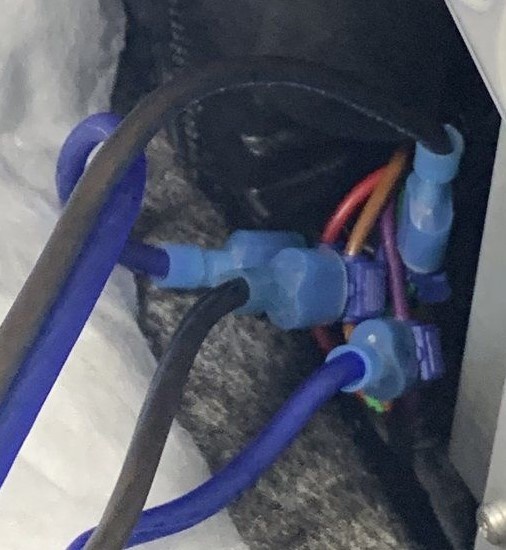
In the end I chose to follow Travis’ diagrams, and this is what I used:
| Channel 1 | Channel 2 |
| Green + | Purple + |
| Red – | Brown – |
Here are a couple photos of my tap:
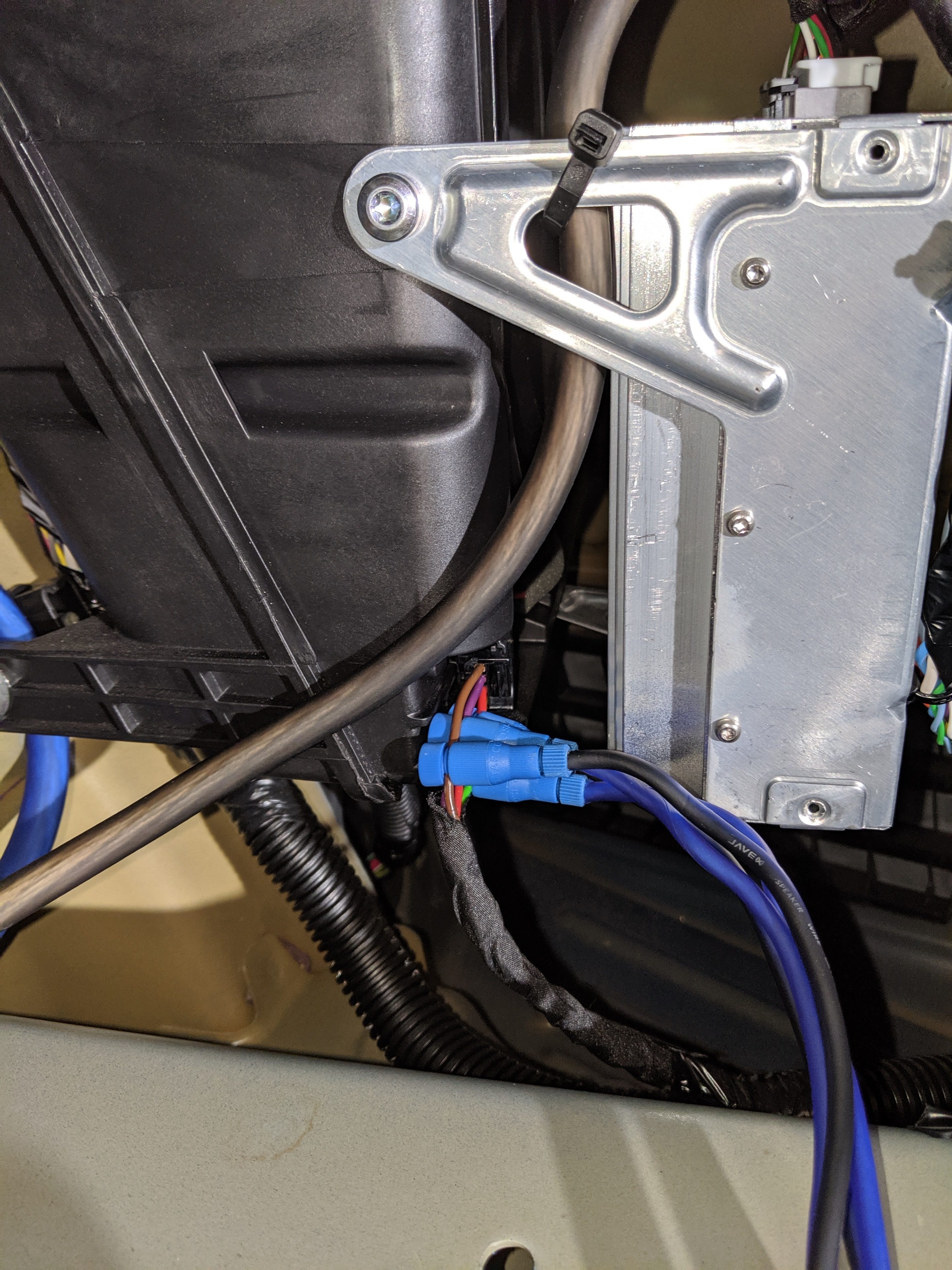
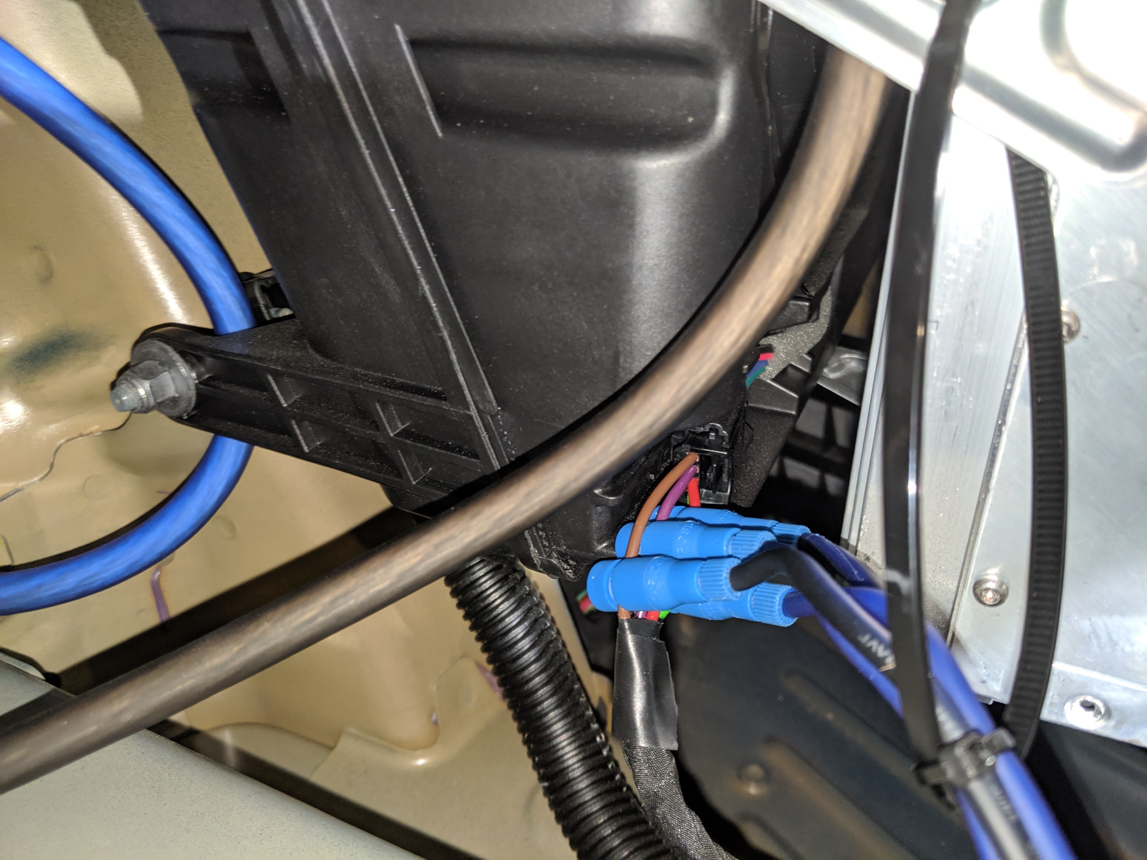
In the picture above you can see that I zip-tied the wires to a larger zip-tie, then attached that to the amplifier frame. This was a bit hoaky, but I couldn’t think of a better way to protect against the wires being pulled and putting too much stress the taps. This ended up being quite valuable when I was reinstalling the trunk liner, since it did tug on the wires quite a bit. I highly recommend doing something similar for your own system.
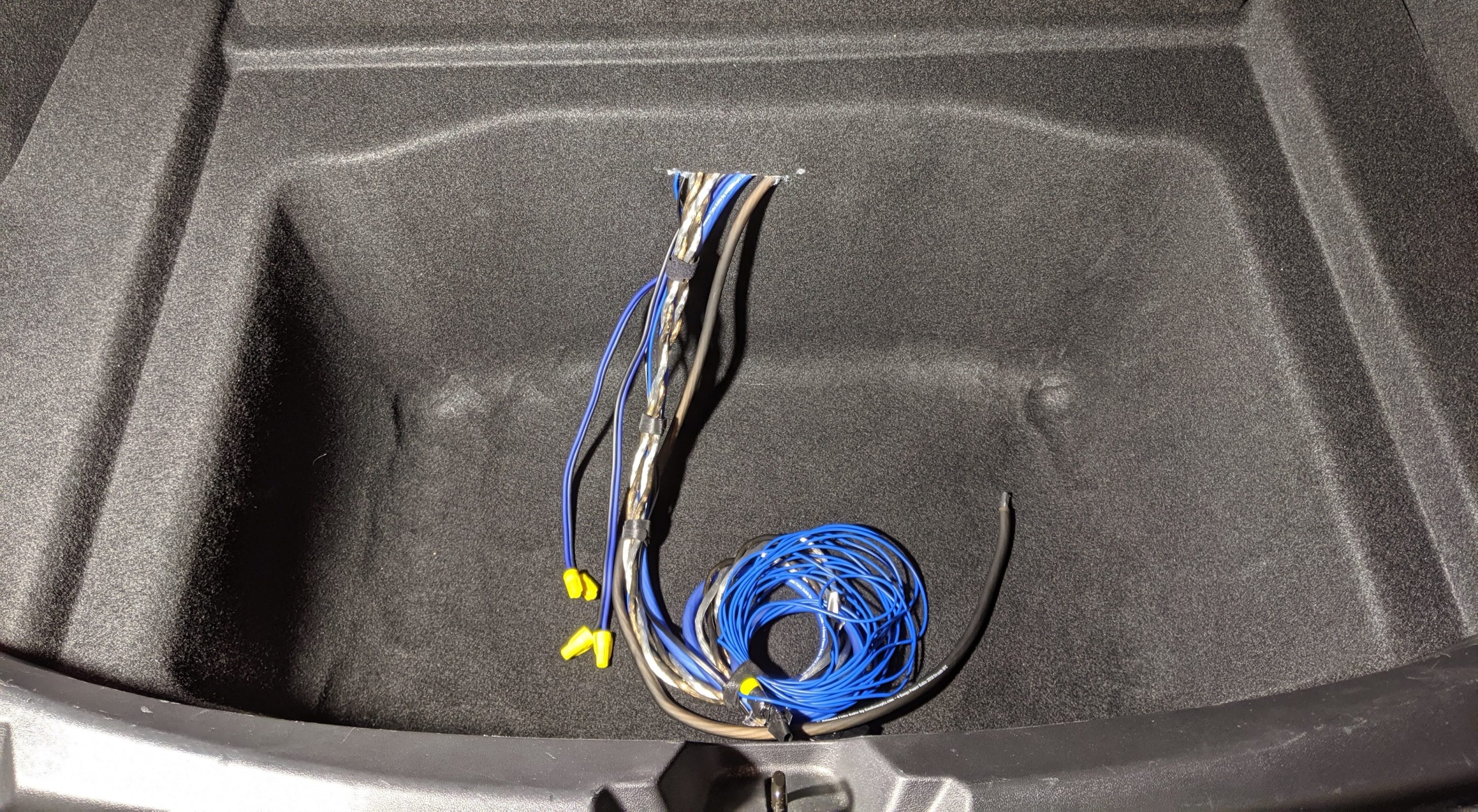
Speaking of the trunk liner, I decided to make a slit in the center of the liner about half-way between the top of the shelf and the main trunk floor. (See Part 2 – Storage for a reference). Here’s what it looked like when I pulled all the wires through:
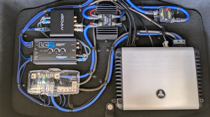
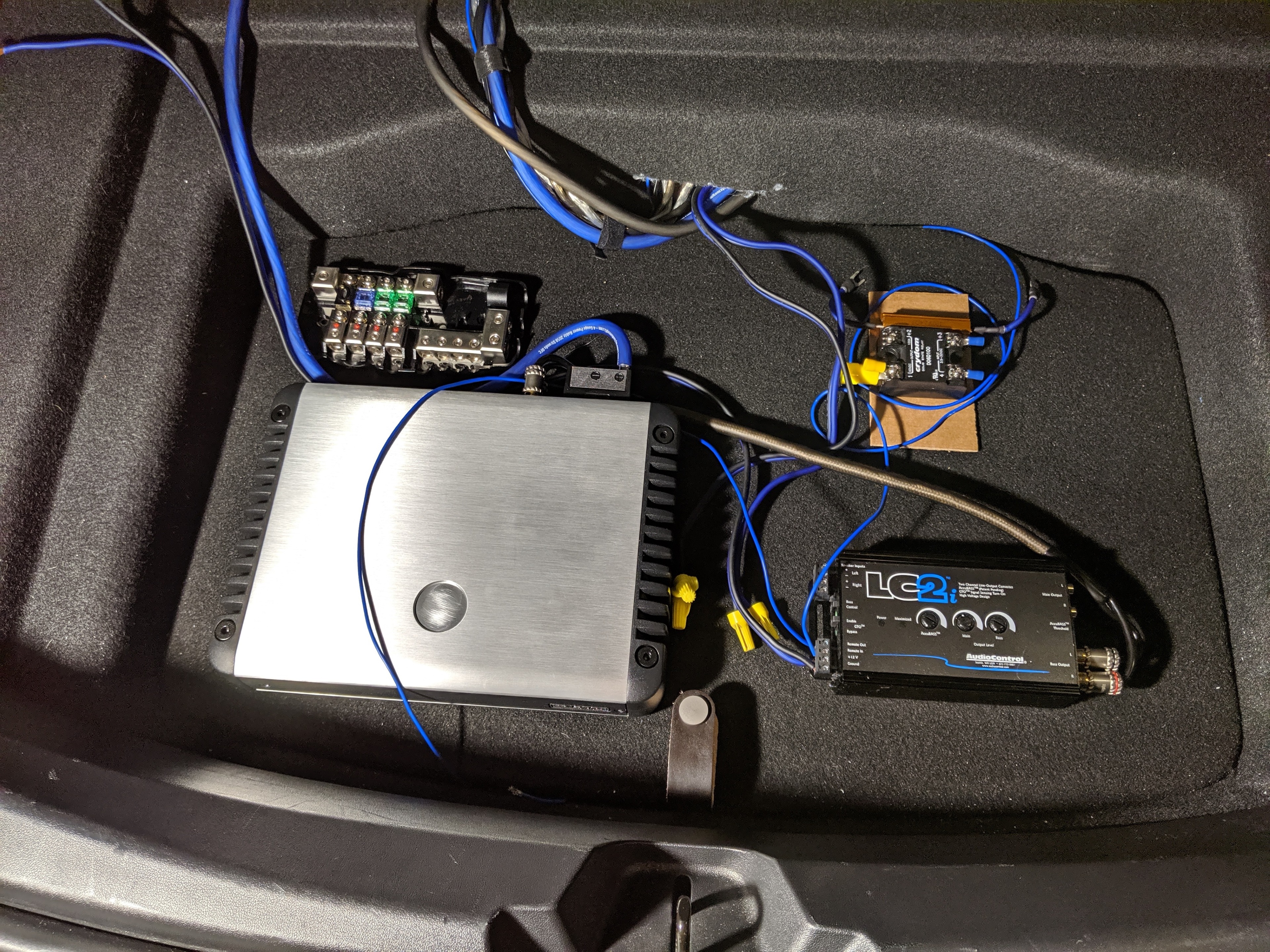
I tried a few different layouts before settling on a final. In this one, for example, I felt that the wires coming out of the fuse block would just be too close to the amp:
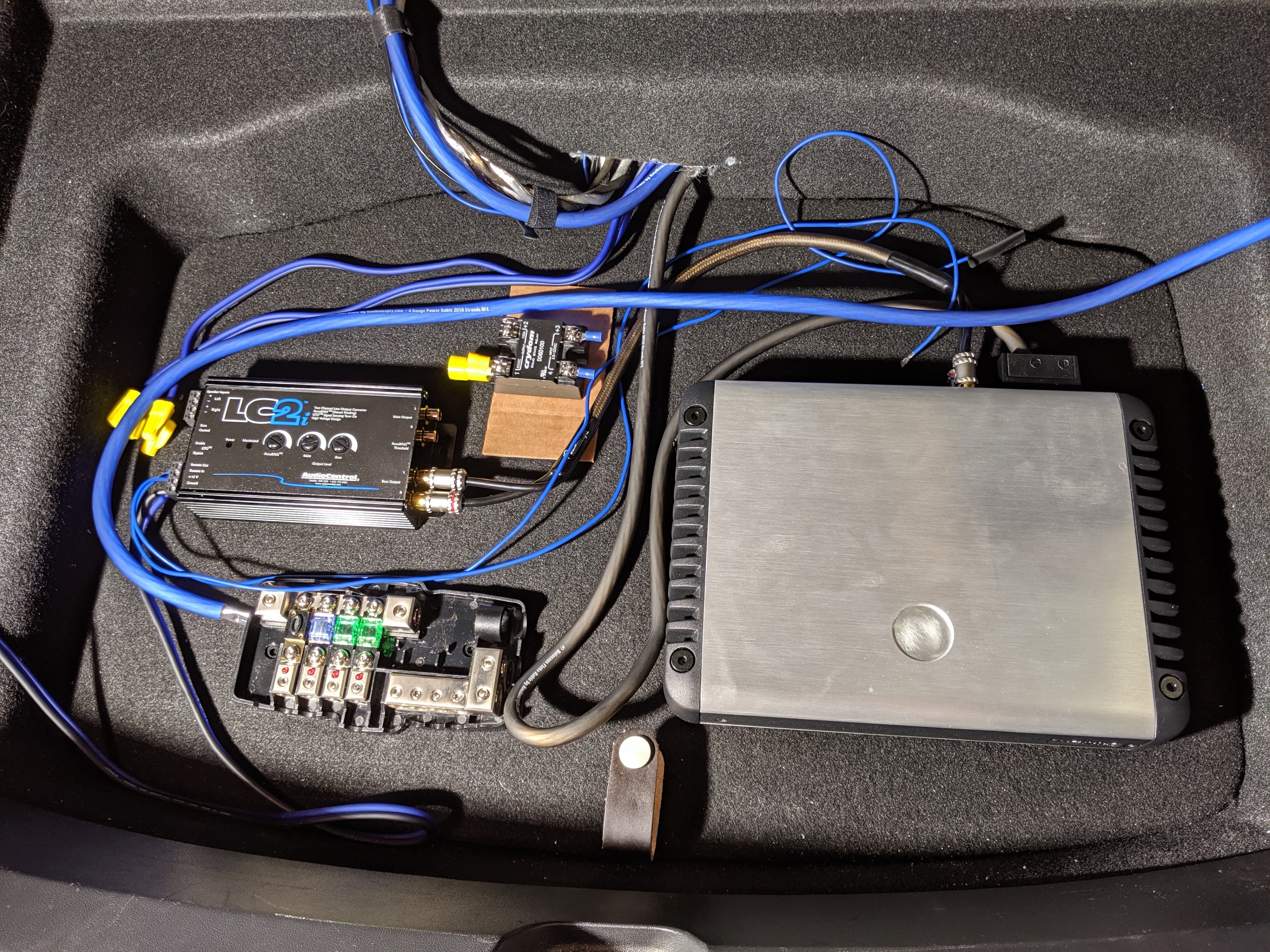
This next one was close to the final layout, but I had the trickle charging circuit between the LC2i and the amp, which ended up being too cramped.
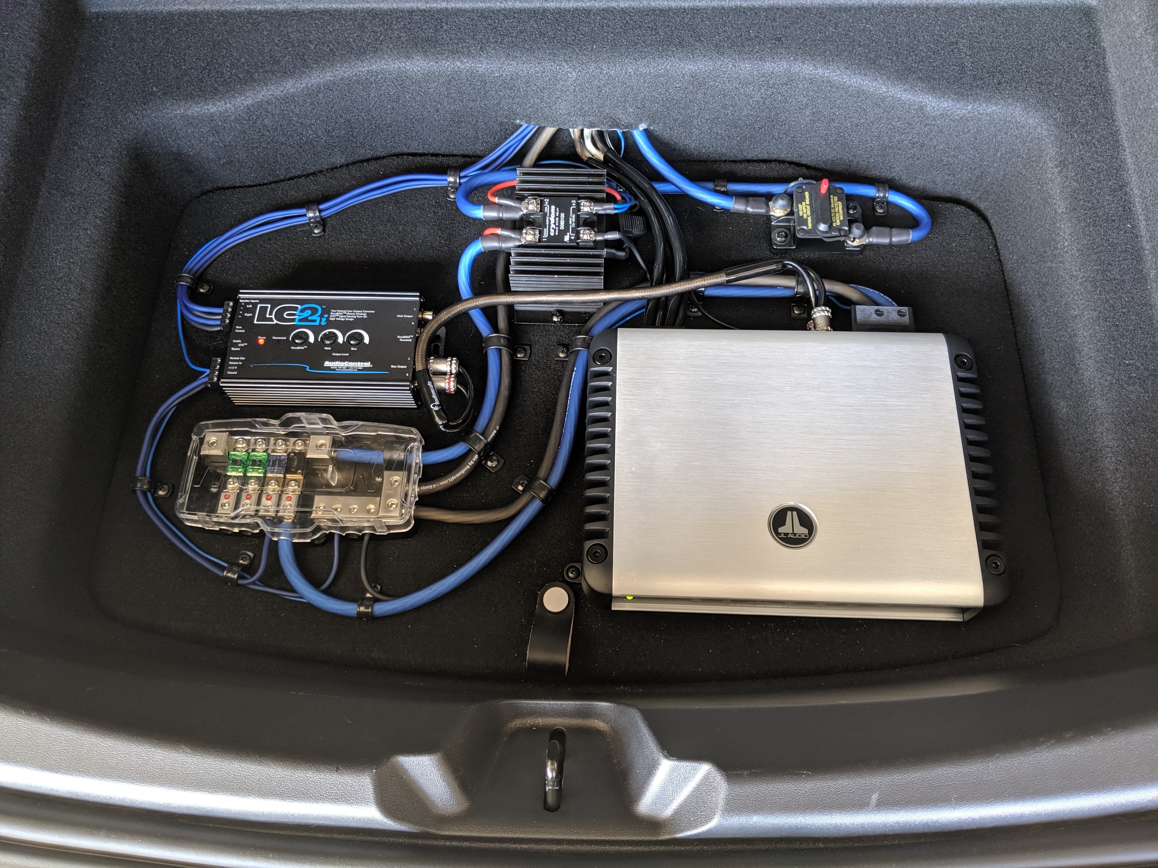
For a few days this actually was my final layout:
I was happy with that layout… but I just wasn’t happy with the sound. I’ll cover this in plenty of detail in Part 7 – DSP, but for now let’s just wrap things up with a picture of the final final layout:
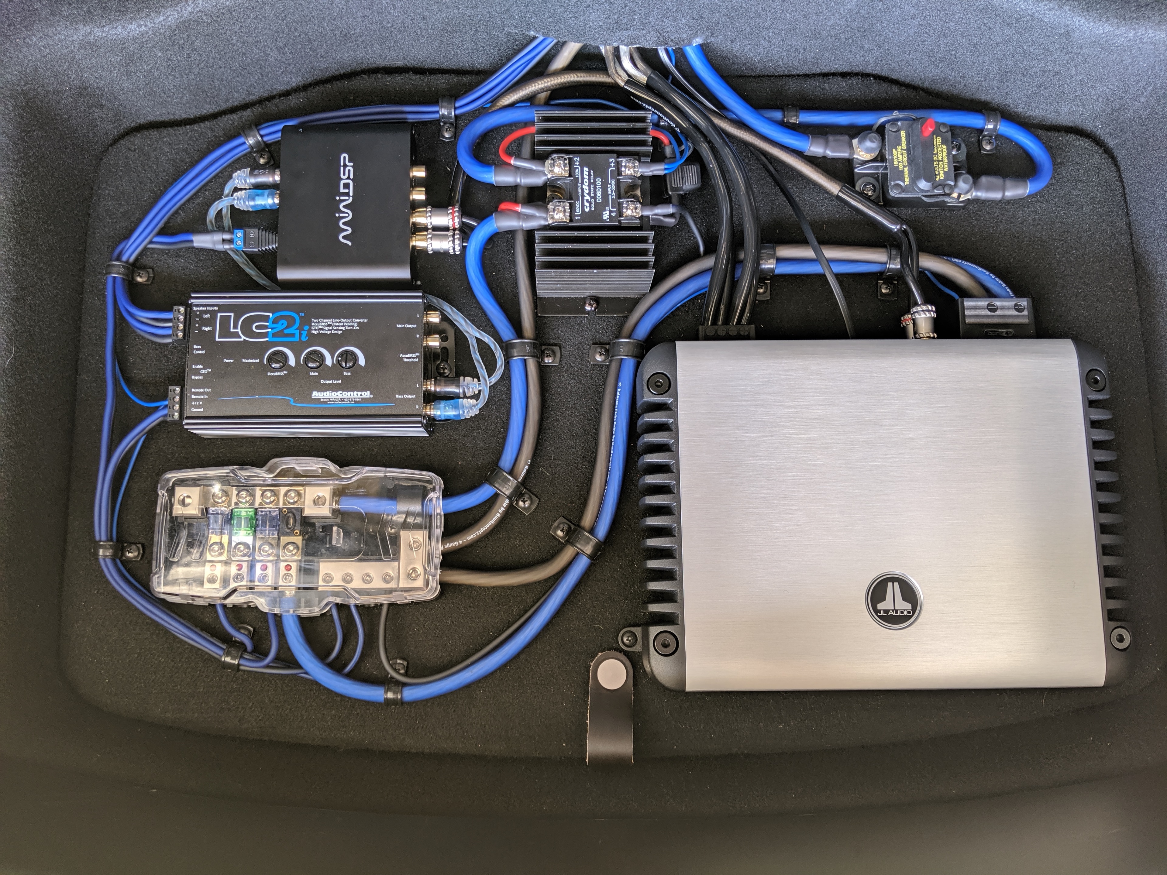
Note that I did add another breaker at the top of my layout. This breaker is in addition to the one near the Penthouse, which I already covered in Part 3 – Power. I added this one as a convenience so I could easily disable all the aftermarket equipment without having to get under the rear passenger seat. I also think it looks cool. 😁
Well, that wraps up Part 4 – Layout. Coming up in Part 5 – Level Control I’ll cover where and how I mounted the Remote Level Control. See you soon!
I can hear you now: “Really? The entire first post in this series is dedicated to an enclosure?” But hear me out. I learned quite
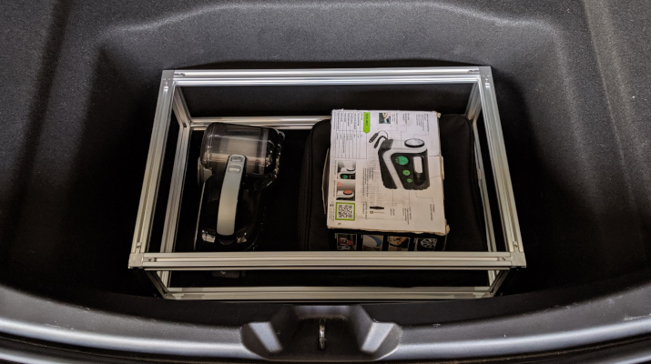
Though I was willing to give up nearly 50% of my trunk, I really didn’t want to give up on storage space entirely. I still